
IO-Link is an internationally standardised communication technology (IEC 61131-9) for the data exchange with sensors and actuators. IO-Link enables the continuous communication from the control down to the lowest field level to the sensor.
EGE is a member of the IO-Link group of companies organised within the PNO (Profibus user organisation). It develops the technology and supports the members and users in the integration of IO-Link enabled products.
The following description of the IO-Link technology explains the key terms and functions.
Further information is available on the homepage of the IO-Link consortium: www.io-link.com.
EGE continuously expands its portfolio with sensors which include the IO-Link functionality. These can be integrated directly via the IO-Link interface in a control system and parametrised comfortably via this connection. As with all standard components, customer-specific special designs are also possible within the framework of the IO-Link specification for products with IO-Link interface.
With the IO-Link master the easy parametrisation of IO-Link enabled sensors is possible. The matching configuration software is available as download from www.iq2-development.com and can be installed on a PC or Notebook. The set includes in addition to the master and power supply also an M12 connection cable to the sensor and a USB cable for connection to the PC.
Talk to our experts for flow and flow sensor technology about your request. Feel free to contact us directly by phone via e-mail or contact form.
Contact usParametrisable sensors and actuators with a standardised interface reduce the multitude of device types required and reduce complexity during procurement.
Only a continuous communication with each sensor and actuator opens up all functions of intelligent devices. This permits the implementation of innovative machine and plant concepts.
IO-Link communication runs over unshielded cables and uses common industry connectors. The installation location can be optimised and the sensor later parametrised within the system. The complete parameter set can be stored in digital form and transmitted freely to additional devices.
IO-Link devices automatically identify and parametrise themselves when changed (data storage). This simplifies the replacement of faulty components and reduces repair-related downtimes of machines and plant.
Intelligent IO-Link devices can be uniquely identified in the system, offer functions for self-diagnosis and supply data for the analysis of the system functionality. This permits novel preventative repair and maintenance concepts.
IO-Link enabled sensors can comfortably be parametrised with a PC/Notebook, an IO-Link master and the corresponding software and can then be used as conventional sensors with switching and analogue output (SIO mode). Alternative their use is also possible as IO-Link devices which supply the sensor signals as process data to a control.
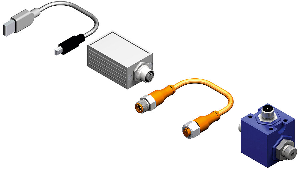
An IO-Link system generally consists of the following components:
The IO-Link master provides the connection between the IO-Link sensor/actuator and the automation system. As part of a peripheral system the IO-Link master is either coupled directly to the PLC in the control cabinet or installed as remote I/O component with field bus connection in the machine or plant. Such masters have several channels which can each be connected to a device with IO-Link functionality.
IO-Link is a serial bidirectional point-to-point communication for the signal transmission and energy supply.
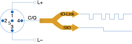
For the connection technology in IP 65 / 67 e.g. M12 plug connectors have been defined. Sensors normally feature a 4 pin connector and actuators a 5 pin connector. IO-Link masters normally feature a 5 pin M12 socket.
The connection assignment has been specified in IEC 60974-5-2 as follows:
In type A the functional assignment for pin 2 and pin 5 is not defined by the IO-Link specification. The manufacturer can use these freely for additional output and input functions. EGE uses pin 2 for an additional switching output, a 4...20 mA output or as signal input.
The connection cable of an IO-Link device to the master should according to the IO-Link specification not exceed a length of 20 m. An unshielded standard cable is sufficient.
The port (pin 4 / C/Q) of an IO-Link master can be operated in the following operating modes:
If the operating mode IO-Link is assigned to the port of an IO-Link master, the communication starts. The IO-Link master supplies a wake-up pulse and waits for the response of the IO-Link partner. After successfully establishing a connection, the master determines the data transmission rate of the device and starts the communication.
The IO-Link specification V1.1 specifies three data transmission rates:
An IO-Link device only supports one of the defined data transmission rates. An IO-Link master according to specification V1.1 supports all data transmission rates and automatically adjusts to the data transmission rate supported by the device.
The response time of an IO-Link system depends on the minimum cycle time of the device and the processing speed of the master. The device description file IODD includes a value for the minimum cycle time.
The IO-Link communication utilises the 24 V level of the switching output for the transmission and is therefore highly interference-resistant. If the IO-Link software detects an error in the data transmission, this is repeated. Only after three consecutive failed attempts is the connection terminated. This termination is reported to the higher level control without delay as an error message.
Generally, four data types are available:
Process data and their value status are transmitted cyclically in a data telegram. The process data lengths has been defined with 0 to 32 bytes for each device in its specification by the manufacturer. The value status indicates whether the process data are value or invalid.
Device data may be parameters, identification data and diagnostic information. They are exchanged acyclically between the master and the device.
If a previously defined event occurs in the device, the occurrence is reported to the master. The master then requests further information from the device and forwards the messages to the control. Events may be error messages and warnings. The IO-Link master can also transmit its own error messages and status data to the control.
The transmission of parameters or events is unaffected by the cyclical transmission of the process data.
Access from application programs to a device is standardised with IO-Link device profiles.
The device profiles define the data structure and content and the basic functionality. Different IO-Link devices are thus provided with a uniform user perspective and an identical program access by the control.
In the IO-Link specification the "smart sensor profile" has currently been defined. It is particularly suited for measuring sensors, because in addition to the switching points measured values are also transmitted.
The manufacturer provides for his IO-Link product an IODD (Input Output Device Description) in the form of XML files and images in digital form. The specified uniform structure of these files ensures the manufacturer-independent universal handling of the data. The IODD contain information about:
For devices which in addition to IO-Link version 1.0 also support version 1.1 there exist accordingly two different IODD versions.
Software provided by the master manufacturer is required to configure an IO-Link system. This software uses the IODD for the communication and parametrisation of an IO-Link device. If multiple masters are used in control systems, the software has additional tasks:
SDNC 500 sensors with IO-Link interface are the smart solution for process monitoring. They can record the flow speed and temperature in fluid mediums.
To do so, there is a configuration software which configures the sensors via an IO-Link/USB master. The ... GAPL models provide flow data for liquid mediums as a linear output signal.
The detection range of sensors suitable for all liquid media can be freely configured. Their output signal is not linear.
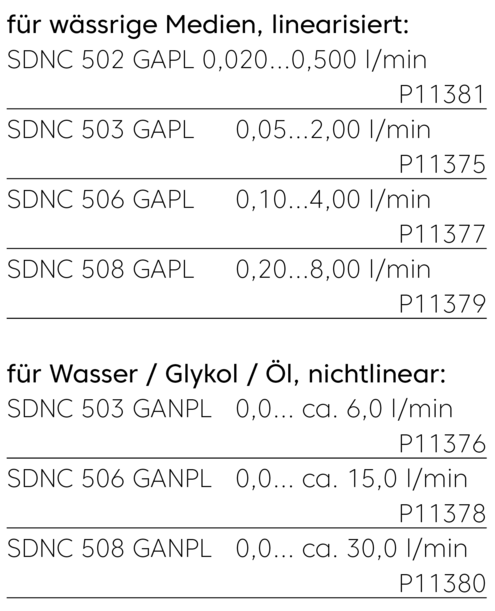
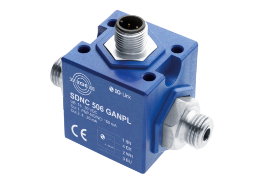
The flow rate sensors have a G1/4 process connection and can be easily integrated with hoses or pipe connectors in pipes. A special flow adapter shapes the flow profile and ensures a stable signal for the SDNC 502/503/506 GAPL.
In the SDNC 508 GAPL a straight inlet section of 100 mm is sufficient to achieve the specifications. The measuring range of the ...GANPL variants can be adapted to almost all media. A non-linear signal path results.
The robust construction makes the sensors not sensitive to moisture and vibrations.
The parametrisation of the sensors is via the IO-Link interface or the buttons on the front panel. Its 6-digit display shows the measurement values which can be sent as process data to an SPS via the IO Link connection. In the IOS mode the user can use the configured analogue and switching outputs.
Functions/parameters
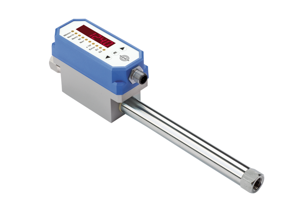
The functional principle of the compressed air sensor is calorimetric. Heat is removed from a sensor element by passing air and results in a temperature reduction. The amount of reduction is determined by the air mass and results in an output signal proportional to the mass flow. No pressure or temperature compensation is required for the medium state. According to factory configuration the flow rate is displayed directly in standard litres or standard cubic metres. The standard conditions for pressure and temperature can be adjusted in the application.
The sensor is inserted inline into the pipe line. The lengths for run-in and run-out distances required result from pipe routes and any existing controls and instruments upstream of the sensor. For the operation of the compressed air meters the air must be free from oil, filtered and dehumidified in accordance with class 1.4.1 as per ISO 8573-1.